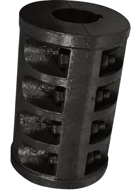
Muff Couplings

Our Products

MUFF COUPLINGS

Reliable Muff Couplings for Industrial Applications

The AniGears Muff Coupling is a robust, rigid coupling designed for the secure connection of two aligned shafts. Also known as a Clamp Coupling, it transmits power through friction grip and keyway engagement, ensuring zero backlash and high torque stability. Its split design allows for easy assembly and disassembly without disturbing the position of the shafts or driven equipment.

AniGears Engineering manufactures high-performance Muff Couplings designed to provide a rigid and reliable connection between two shafts for efficient power transmission. Engineered with precision and manufactured using premium-grade materials, our muff couplings ensure maximum strength, accurate shaft alignment, and dependable performance across a wide range of industrial applications.

Our Muff Couplings are built to withstand heavy loads, continuous operation, and demanding working environments. With excellent dimensional accuracy and superior machining, they deliver smooth torque transmission while reducing wear and maintenance requirements. Their robust construction ensures long-lasting durability and consistent operational efficiency.

AniGears’ AM Series Muff Coupling is a rigid, split-sleeve coupling built to lock two precisely aligned shafts into a single, zero-backlash drive line. Manufactured in two-piece cast iron construction across eighteen sizes — AM-25 through AM-120 — it clamps directly onto the shaft using key engagement and friction grip, so neither shaft needs to be shifted axially during fitting or removal. AniGears manufactures the AM Series in Kolkata for line-shafting and heavy-duty power transmission drives across India.

Get a Quote Download Catalogue
Selection Procedure

Easy Selection Steps

Sizing an AM Series muff coupling follows the same logic used across AniGears’ coupling range, applied against the dimension and torque-rating table below.

01
Determine Absorbed Power (kW)

read this from the driven equipment’s actual duty point, not the motor nameplate rating. For constant-load line shafting the two are usually close, but confirm against the equipment datasheet.

02
Select Service Factor (SF)

apply a service factor appropriate to the duty; steady, continuously loaded drives use a lower factor than intermittent or shock-prone drives.

03
Compute Design Power

multiply absorbed power by the service factor to get the design power the coupling must be rated for.

04
Determine Coupling Rating at Operating Speed

check the torque rating (kgf.m) of each AM size in the table below against your shaft speed.

05
Select Coupling Size

choose the smallest AM size whose torque rating meets or exceeds your design power.

06
Verify Bore and Misalignment

confirm both shaft diameters fall within the selected size’s bore range, and confirm the application has effectively zero ongoing misalignment.

07
Finalize Coupling Type

confirm the size against the dimension table, then contact our engineering team to finalize bore, keyway, and bolt specification.

Because a muff coupling is rigid, Step 6 matters more here than it would on a flexible coupling there is no elastomeric element to absorb an error in alignment.

Dimension Of Muff Couplings

Detailed Measurements for Muff Couplings

Accurate dimensions provided to ensure proper selection, installation, and reliable performance of your muff couplings.

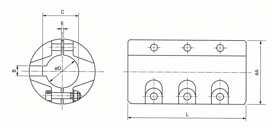
The table below covers the full AM Series range, from AM-25 (Ø25 mm bore) to AM-120 (Ø120 mm bore). Bore (ØD) is held to H8 tolerance and keyway width (B) to js9 — the two tolerances that keep the key a low-clearance, backlash-free fit. Torque ratings are given in kgf.m, and the Bolt column states clamping bolt quantity, thread size, and length; for example, “4-M6 × 30L” means four M6 bolts, 30 mm long. Use this table together with the selection steps above to confirm the correct size before ordering.

Size Bore ØD (H8) A L Key Way Bolt Torque (kgf.m) Weight (kg)
B (js9) C Key (b × h)
AM-25 Ø25 H8 Ø50 88 7 28 7×7 4-M6 × 30L 22 1
AM-30 Ø30 H8 Ø60 105 7 33 7×7 4-M6 × 30L 30 1.5
AM-35 Ø35 H8 Ø70 120 10 38.5 10×8 4-M8 × 35L 40 2.5
AM-40 Ø40 H8 Ø80 140 10 43.5 10×8 6-M10 × 40L 55 3.9
AM-45 Ø45 H8 Ø90 160 12 48.5 12×8 6-M10 × 45L 70 5.6
AM-50 Ø50 H8 Ø100 176 12 53.5 12×8 6-M10 × 45L 95 7.2
AM-55 Ø55 H8 Ø110 180 15 60 15×10 6-M10 × 45L 120 9.6
AM-60 Ø60 H8 Ø120 184 15 65 15×10 6-M12 × 50L 150 11.6
AM-65 Ø65 H8 Ø130 200 18 69.4 18×11 6-M12 × 50L 205 12.2
AM-70 Ø70 H8 Ø140 214 18 74.4 18×11 6-M14 × 55L 245 15.7
AM-75 Ø75 H8 Ø150 240 20 79.9 20×12 6-M14 × 55L 300 20.6
AM-80 Ø80 H8 Ø160 264 20 84.9 20×12 6-M16 × 55L 360 21.5
AM-85 Ø85 H8 Ø170 278 24 93 24×16 6-M16 × 55L 435 27.4
AM-90 Ø90 H8 Ø180 292 24 98 24×16 6-M18 × 75L 530 30
AM-95 Ø95 H8 Ø190 300 24 103 24×16 6-M18 × 75L 615 37.5
AM-100 Ø100 H8 Ø200 320 28 106.4 28×16 6-M18 × 75L 690 42
AM-110 Ø110 H8 Ø210 360 28 116.4 28×16 6-M18 × 75L 900 56
AM-120 Ø120 H8 Ø280 410 32 127.4 32×18 8-M20 × 75L 1,100 85
Specifications

Technical Specifications

  • Body Material: High-Grade Cast Iron Grade 20.
  • Bolts: Equipped with precision-engineered Mild Steel (MS) Bolts.
  • Design: Two-piece split construction (shell) for simplified maintenance and installation
Applications

Key Applications

  • Ideal for line shafting in textile mills, rolling mills, heavy engineering machinery, and power transmission setups where shaft alignment is precise
  • AniGears’ AM Series muff couplings are specified wherever two shafts run in permanent, accurate alignment and a rigid, backlash-free drive is required:
    • Line shafting in textile spinning and weaving mills
    • Rolling mills and steel re-rolling plants
    • Sugar mill drive lines
    • Pumps and blowers
    • Conveyor drive shafts
    • Agitators and mixers
    • General heavy-engineering power transmission where alignment is fixed
  • The common thread across these applications is fixed, close-tolerance shaft alignment. Muff couplings are not selected for drives where alignment shifts during operation or where the machine sees regular shock loading. Sectors flagged above should be confirmed as active AniGears customer segments before this section is published.
product-image
Muff Coupling

What Is a Muff Coupling?

A muff coupling is a rigid shaft coupling that joins two co-axial shaft ends inside a single outer sleeve, so the two shafts rotate together as one continuous line. It is also called a clamp coupling, sleeve coupling, box coupling, or split muff coupling, depending on the manufacturer and the region.

The term is used loosely across the industry for two different designs. The older, simpler version is a solid, one-piece sleeve that is heated, slid over both shaft ends, and cooled into place — a method that gives no way to inspect or adjust the joint once it is fitted. AniGears manufactures the split, two-piece version instead: a Cast Iron sleeve machined in two halves that bolt together around the shafts. It provides the same rigid, zero-backlash connection as a solid muff coupling, but allows straightforward fitting, inspection, and removal without heating equipment or disturbing either shaft’s position.

Muff Coupling

How a Muff Coupling Works

Each shaft end sits inside one half of the split sleeve, with a machined key seated in matching keyways cut into both the shaft and the sleeve bore. The key locks the sleeve to each shaft rotationally, so torque has a direct metal-to-metal path from the driving shaft, through the key, into the sleeve, and out through the second key into the driven shaft.

The two sleeve halves are then drawn together with clamping bolts. As the bolts are tightened, the sleeve grips the shaft surface under friction, in addition to the load already carried by the keys. Between the key engagement and the friction clamp, the joint has effectively no rotational play which is why muff couplings are specified wherever a rigid, zero-backlash connection matters more than flexibility.

Material Selection

Construction & Materials

AniGears manufactures the AM Series sleeve in High-Grade Cast Iron Grade 20, a material chosen for muff couplings because it damps vibration well, resists wear under repeated clamping and unclamping, and machines to a tight bore tolerance at a lower cost than forged steel. The clamping bolts are Mild Steel (MS), selected for consistent clamping load across the bolt’s working life. The bore is held to an H8 tolerance and the keyway to js9 — the tolerance band that keeps the key a controlled, low-clearance fit in both the shaft and the sleeve, which is what allows the coupling to run without perceptible backlash.

  • Body Material: High-Grade Cast Iron Grade 20
  • Bolts: Precision-engineered Mild Steel (MS) bolts
  • Design: Two-piece split construction (shell) for simplified maintenance and installation
Advantages

Advantages of AniGears Muff Couplings

The split design gives the AM Series a specific set of advantages over both solid-sleeve muff couplings and flexible coupling types:

  • Simple two-part construction (sleeve plus key) that is straightforward to specify, stock, and service
  • Smooth, compact external profile with no projecting bolts or arms, which is safer to work around on running line shafts
  • Smaller radial footprint than an equivalent flange coupling, useful in tight enclosures and pillow-block runs
  • Split construction allows the coupling to be fitted or removed without shifting either shaft axially, unlike a solid-sleeve muff coupling
  • Zero-backlash torque transmission from the combined key-and-friction grip, with no elastomeric element to wear out
  • Lower installed cost than a flexible coupling of equivalent torque rating, where the shafts are already accurately aligned
Choose Muff Coupling

When to Choose a Muff Coupling and When Not To

A muff coupling is the right choice when both shafts are already accurately aligned and will stay that way. It is a rigid coupling, so it does not flex any misalignment in the drive line is transmitted directly into the connected bearings and machine casings rather than absorbed at the coupling.

For the same reason, a muff coupling is not the right choice where the application involves angular or parallel misalignment, shock loading, or variable and pulsating torque. In those conditions a flexible coupling is the safer specification. AniGears’ Jaw Couplings use a resilient elastomer spider to absorb shock and moderate misalignment, while the AP Series and AB Series Pin Bush Couplings use elastomeric bushes to damp vibration on pumps, fans, and other variable-load drives. Talk to our engineering team if you’re not sure which category fits your application.

Difference

Muff Coupling vs Other Coupling Types

Muff couplings sit at the rigid end of AniGears’ coupling range. The table below compares the AM Series against AniGears’ flexible coupling types, so you can confirm you’re specifying the right category before working through the sizing steps above.

Parameter Muff / Clamp Coupling (AM Series) AG / EA Series Gear Coupling Jaw / Resilient Coupling
Rigidity Fully rigid Torsionally rigid, mechanically flexible Torsionally flexible
Misalignment tolerance None — shafts must already be aligned Angular + parallel + axial Angular + parallel + limited axial
Shock absorption None Limited (metal-to-metal, torsionally rigid) Good — elastomer element damps shock
Typical use case Fixed-alignment line shafting, rolling mills High-torque heavy industry drives Pumps, motors, moderate-torque drives
Get a Quote Download Catalogue
Maintenance

Installation & Maintenance Notes

Before fitting an AM Series muff coupling, confirm shaft alignment is within the tolerance required for a rigid joint a muff coupling cannot correct misalignment introduced at installation. Tighten the clamping bolts in a criss-cross sequence, working gradually around the sleeve rather than fully tightening one bolt before moving to the next, so the two sleeve halves seat evenly. Keep the shaft and sleeve mating surfaces free of oil or grease, since the coupling’s friction grip depends on clean, dry contact between the sleeve and the shaft.

Why Choose

Why Choose AniGears

AniGears Engineering Solutions has been manufacturing power transmission components since 2007, and is certified to ISO 9001:2015 with NABL-accredited lab testing on its production. The company supplies established industrial sectors including Steel, Cement, Power, Mining, Paper, and Heavy Engineering, and manufactures the AM Series alongside nine other coupling ranges — Tyre, AP and AB Series Pin Bush, AG and EA Series Gear, Resilient, Jaw, and both Brakedrum coupling types — so a single supplier can cover a full plant’s coupling requirements.

FAQ's

Frequently Asked Questions

A muff coupling rigidly connects two accurately aligned shafts for zero-backlash torque transmission, commonly in line shafting, rolling mills, and other fixed-alignment industrial drives.

“Muff coupling” and “clamp coupling” describe the same split, two-piece design. “Split muff coupling” is the term used to distinguish it from the older, solid one-piece sleeve type.

The AM Series sleeve is High-Grade Cast Iron Grade 20, clamped with Mild Steel bolts, and machined to an H8 bore tolerance with a js9 keyway tolerance.

The AM Series covers bores from Ø25 mm (AM-25) to Ø120 mm (AM-120), with torque ratings from 22 kgf.m up to 1,100 kgf.m.

No. A muff coupling is a rigid coupling and requires the two shafts to already be accurately aligned. For misaligned or shock-loaded drives, choose a Jaw or Pin Bush Coupling instead.

Determine the absorbed power, apply the correct service factor, and match the resulting design power against the torque rating in the AM Series dimension table at your operating speed.
Get a Quote Download Catalogue
Download Catalogue

Engineering Solutions Catalogue

Download our comprehensive catalogue to explore Anigears’ full range of engineering products, including couplings, pulleys, and conveyor solutions. Get detailed specifications, dimensions, and application information to help you select the right solution for your industrial needs.

Download Catalogue
Scroll Up